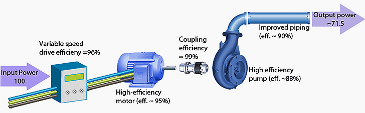
Pump as part of the process
Pumps are always part of the pumping system when used. (Pump flow control)
A pumping system is always a network of pipes, tanks, valves and other parts of the system. The receiver is always at a higher geographical level than the system supply. These parts can be on the same level as each other, like a closed circuit heat transfer system.
Pumping systems almost always require a change in flow rate or a change in flow. Pumping applications provide us with the most diverse methods of energy storage.
Examples include the daily drinking water cycle, the variable liquid demand process, or the seasonal heating demand. Of course, these changes can be in the pump head, such as periodic changes in process pressure or in pumping into tanks with a variable fluid level.
Despite these changes, the pump capacity is selected based on the maximum flow and pump head, or it may even be based on future needs with a safety margin.
The average pumping capacity may be just a fraction of the maximum capacity, and this requires some kind of control, and it must be controlled.
Pump flow control methods
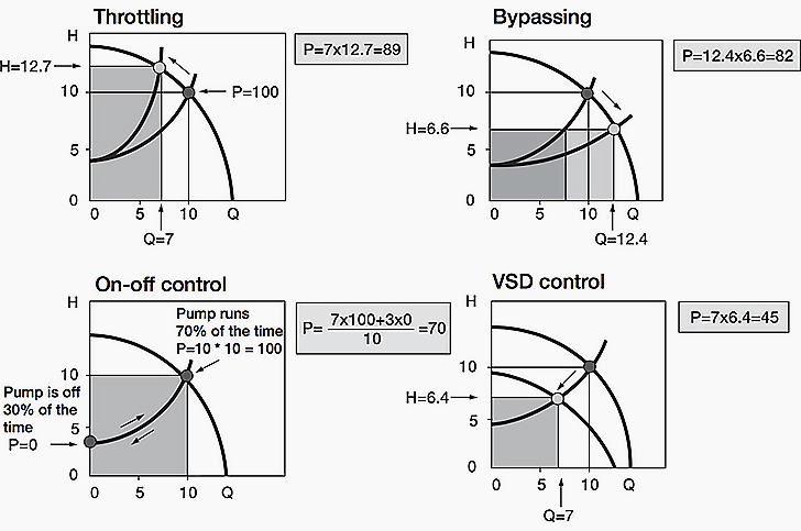
There are several different ways to adapt the flow to the requirements of the system. The four most common methods of controlling the flow of pumps are the use of control valves, the use of a bypass, the on-off control and the variable frequency drive (VFD). These methods are shown in Figure 1.
Figure 1. Demonstration of pump flow control methods – A – control through control valves, B – use of bypass, C – control on – off and D – control of variable speed drive.
The relative power consumption of these different control methods can be obtained from the area between the x and y axes and the working point.
This relationship is used:
P=Q×H
In the example below (see Figure 2), the relative power consumption of the average flow rate of 70% is calculated by various control methods. A detailed description of power consumption and energy savings for different pumping applications will be described in future articles.
Power consumption of four flow control methods
| Control method | Energy consumption |
| Control through control valves | 89 |
| Use bypass valves | 82 |
| On-off control | 70 |
| Variable speed drive control | 45 |
Control through control valves
Throttling
Control through control valves is the most common method used. The current created by the constant speed pump is reduced by increasing the losses in the system by closing the valve. In the example, Figure 2 the working point is displaced from (Q = 10, H = 10) to (Q = 7, H = 12.7).
Relative power consumption can be calculated from the following equation:
P = 7 × 12.7 = 89
Use a bypass
Bypassing
Although not very common, the bypass is basically applied to rotary pumps. The discharge flow to the system is reduced by bypassing part of the pump discharge flow to the pump suction, meaning that the total flow increases (from 10 to 12.4) but the head decreases (from 10 to 6.6).
Relative power consumption is equal to:
P = 12.4 × 6.6 = 82
On-off control
On-off control is used when no non-step control is required, such as maintaining the pressure in the tank between pre-set limits. This pump is either running or stopping.
Relative power consumption can be easily obtained as follows:
P = 0.7 × 100 = 70
Variable speed drive control
VFD control
In order to understand the benefits of VFD, consider the curves in Figure 2. With low static head systems, the optimal efficiency of the pump follows the system curve. Using variable speed drive control, the pump operating point follows from the curve without changing the system.
Changing the pump speed shifts the pump curves according to the continuity rules. If the pump impeller speed is reduced, the pump curve will move downward. If the speed increases, it moves upwards. This means that the pumping capacity is matched exactly to the requirements of the process. Based on our previous example, both the flow rate (from 10 to 7) and the head (from 10 to 4.6) are reduced.
Relative power consumption can be calculated as follows:
P = 7 × 6.4 = 45
This example shows that the variable speed control method is the most effective energy method in pumping applications. The examples discussed were calculated for only one flow rate (70%), while the relative power consumption with different control methods depends on the flow rate. This relationship is shown in Figure 3 (Figure below).
In these curves, the efficiency of the pump, motor and drive are also considered, and for this reason, the results are somewhat different from what is shown in Figure 2.
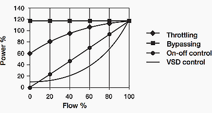
Figure 3. Power consumption for different pumping control methods as a function of flow rate. Percentage values of flow and power are related to nominal pump values.
When the operating system is running at a reduced flow rate, control based on the use of the control valve results high losses in pump and valve. These losses in motor remain almost constant throughout the entire flow range. In variable speed drive control, the operating point follows the system curve which has been optimized for pump efficiency. In general, according to the rules of continuity, energy consumption drops significantly when speed is reduced.
Energy saving with variable speed drive control or VFD is remarkable.