Mechanical Seal
This article provides the background required to specify shaft sealing systems (mechanical seal) for centrifugal and rotary pumps. Sealing systems to minimize worker exposure, mitigate safety concerns and reduce fugitive emissions are included.
Seal Type
Type A seal is a balanced, internally-mounted, cartridge design, pusher seal with multiple springs. Secondary sealing elements are elastomeric O-rings
Type B seal is a balanced, internally-mounted, cartridge design (metal bellows) seal. Secondary sealing elements are elastomeric O-rings. seal. A metal bellows seal offers the advantage of having only static secondary seals. It may be specified instead of the default Type A seal for low-temperature service.
Type C seal is a balanced, internally-mounted, cartridge design (metal bellows) seal. Secondary sealing elements are flexible graphite. Bellows seals are inherently balanced. Stationary metal bellows seals are the primary choice for high-temperature Arrangement 1 seals.
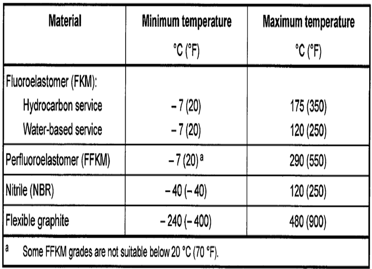
Temperature limit guide for secondary seal material:
Arrangements and level of control:
In order to further control the leak, mechanical seal can be formed using different back-up devices, which these different devices are known as arrangement. According to API 682, there are three arrangements for mechanical seal.
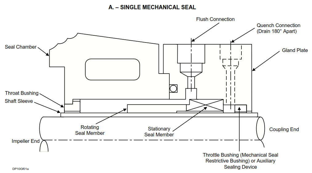
Arrangement 1: Single Mechanical seal
It consists of a mechanical seal and a Restrictive Non-contacting Bushing following a mechanical seal. The bush remains at a fixed distance from the shaft and therefore keeps the leakage confined, even in the event of a mechanical seal failure. Restrictive Bushing can be assembled in three ways.
Arrangement 1 is often used in streams that are not very environmentally friendly.
Arrangement 2:
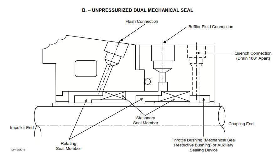
Seal configuration having two seals per cartridge assembly, with the space between the seals at a pressure less than the seal chamber pressure.
It consists of a pair of complete mechanical seal without positive pressure (Unpressurized). The outer seal, or atmospheric seal, is called the containment seal, and the space between the inner and outer seal is called the containment seal chamber. The pressure containment chamber is less pressurized than the pressure chamber and inside the pump. This layout used to be called the Tandem arrangement.
According to API 682, Buffer Fluid may be injected into the containment seal chamber or may not be injected. If the containment seal or the external seal is of a wet seal design (Wet Seal Design), liquid buffer fluid is used and Plan 52 is used, and if the containment seal is of the Dry-running Seal type, gas is used as a buffer fluid.
Arrangement 2: Unpressurized Dual Seal
Arrangement 3:
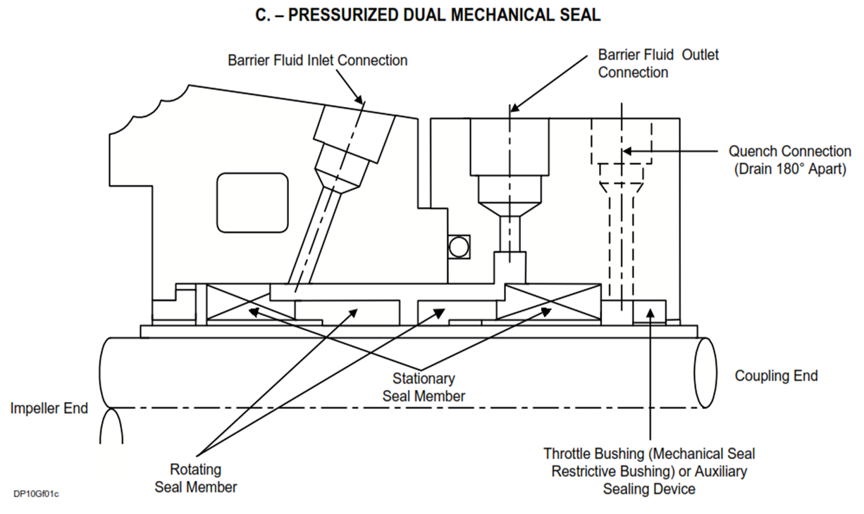
Seal configurations having two seals per cartridge assembly, utilizing an externally supplied barrier fluid at a pressure greater than the seal chamber pressure.
Pressurized Dual Seal (Figure C), uses two complete seals (regardless of orientation) with a barrier fluid injected between the seals. The barrier fluid is required and must be at a higher pressure than the pressure in the pump. The barrier fluid may be a liquid or a gas. For liquid barrier fluid there may be a reservoir, piping and leakage detection instrumentation similar to an unpressurized dual seal termed an API flush plan 53. Liquid may also be supplied from a circulating system or other process source in which case the plan is termed flush plan 54. When a gas (almost always nitrogen) is used as the barrier it is termed API flush plan 74. Pressurized dual seals offer the highest level of leakage control and provide the highest reliability in hot and or dirty services.
Category
In an effort to expand the application of API 682 seals to other industries, the concept of seal categories was developed.
Category 1 seals are intended for use in non-API 610 pump seal chambers, meeting the dimensional requirements of ASME B73.1, and ASME B73.2 seal chamber dimensions and their application is limited to seal chamber temperatures from –40 °C (–40 °F) to 260 °C (500 °F) and gauge pressures up to 2 MPa (20 bar) (300 psi).
Category 2 seals are intended for use in seal chambers meeting the chamber envelope dimensional requirements of API 610. Their application is limited to seal chamber temperatures from –40 °C (–40 °F) to 400 °C (750 °F) and gauge pressures up to 4 MPa (40 bar) (600 psi).
Category 3 provides the most rigorously tested and documented seal design.They meet the seal chamber envelope requirements of API 610 (or equal). Their application is limited to seal chamber temperatures from –40 °C (–40 °F) to 400 °C (750 °F) and gauge pressures up to 4 MPa (40 bar) (600 psi).
Reference: Exxon Mobil